Data centers that deliver critical services for businesses have always been concerned with costly downtime. Around 2005, there was a surge in the number of servers in a data center, drastically impacting power requirements and cooling concerns. Shortly after, with the downturn of the economy, power and cooling efficiency began to take precedence over downtime. Designing for efficiency by only considering power and cooling strategies is short-sighted. There are other efficiencies that will enhance the data center’s ability to cost effectively adapt to business strategy changes and increased computing demand. A data center solution that considers and designs for the five key elements; performance, time, space, experience and sustainability, will be reliable, flexible, scalable and efficient in many ways beyond just cooling and power.
Element #1: DATA CENTER Performance
When companies began adopting high density configurations, virtualization and other methods to boost the capacity of existing IT equipment, they disregarded the need for a robust data center infrastructure to ensure uninterrupted business-critical applications. Infrastructure can have a direct impact on network performance. Ethernet networks can experience several different problems including slow response time, application sluggishness, and even a loss of link connection. In a study of 67 data centers with a minimum size of 2,500 square feet, done by the Ponemon Institute in 2013 (sponsored by Emerson Network Power), the average cost of data center downtime across industries was approximately $7,900 per minute. This was a 41 percent increase from $5,600 in 2010. To maximize network performance three parts of the infrastructure must be considered: the structured cabling, racks and cabinets, and the cable management.
Maximizing the structured cabling channel performance takes more than just selecting the best performing connectivity and cable in the market. This is because the TIA component performance is specified as a range, not a single value, so the channel performance becomes an average. Also, design decisions in the cable can negatively impact the performance of the connector and vice-versa. To maximize channel performance with the most headroom, the connectivity and cable components should be co-engineered. Insertion loss should also be minimized. This is especially critical with fiber systems since the loss budgets for 40 and 100 Gigabit Ethernet can easily be exceeded, even if components meet the maximum insertion loss specified by the TIA standards.
Maximize channel performance with co-engineered cabling and connectivity.
Active equipment will change at least once, usually several times, during the life of the physical infrastructure. In fact, 90% of active equipment will be replaced in five years or less (Source: BSRIA, 2011). Right-sizing the rack or cabinet initially is not difficult, but the rack or cabinet must be able to adjust to accommodate new equipment with different size and weight requirements. Look for features like adjustable side rails and higher weight thresholds.
Airflow may also change since some equipment breaths side-to-side instead of front-to-back – rising temperatures will negatively affect network performance. The mixing of cold and hot air will decrease the efficiency of the cooling solution. The rack or cabinet should have options that help manage airflow like baffles that can be easily added for equipment with side-to-side airflow, blanking filler panels to fill open rack units and brush grommets (or something similar) at the cable entrance and exit points. This will minimize the mixing of hot and cold air to help maximize the efficiencies of the cooling solution.
Physical support should be flexible and scalable to accommodate new equipment and have options to help manage airflow.
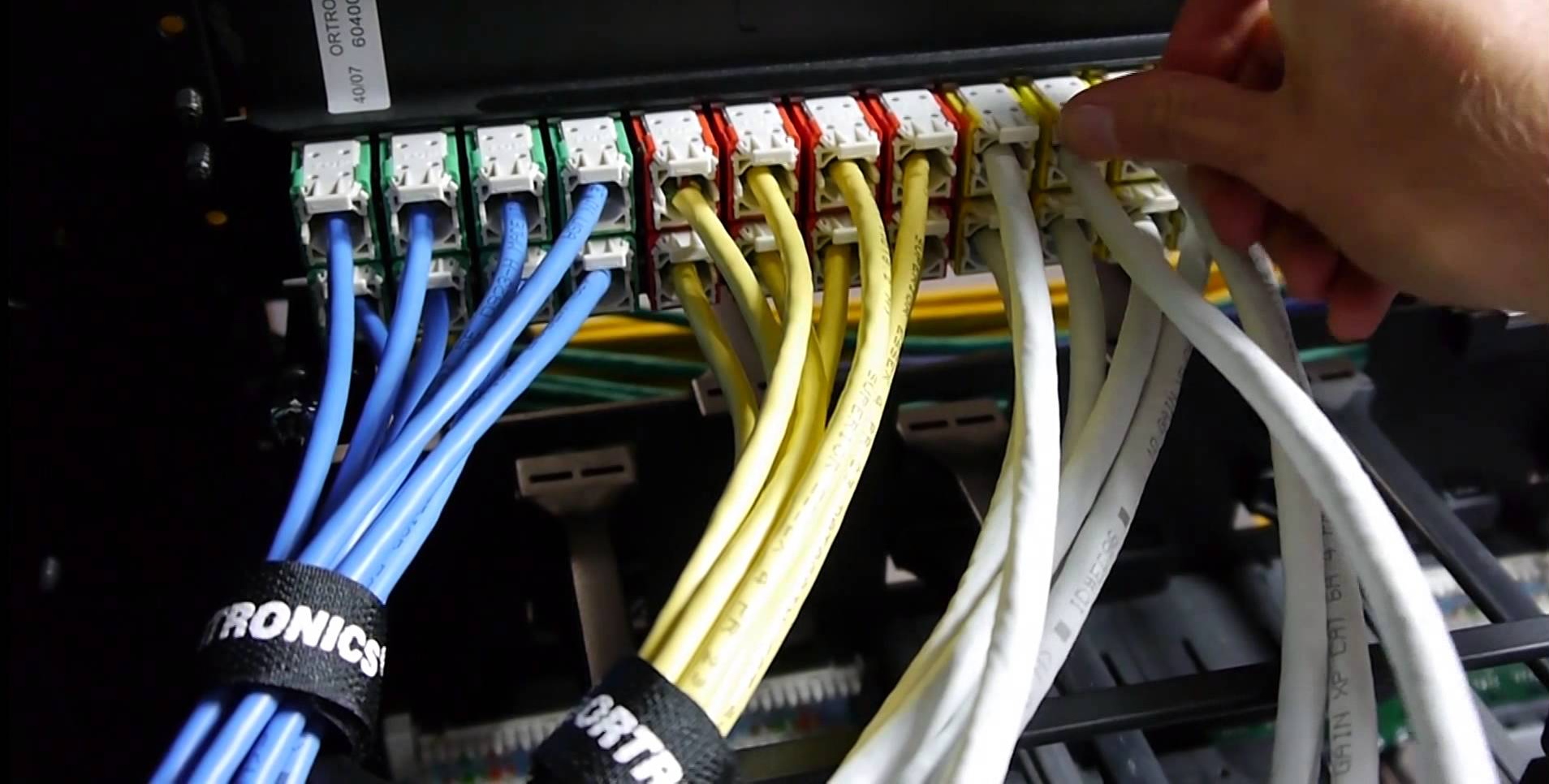
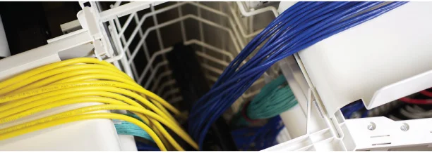
The last component of the infrastructure is cable management. The infrastructure must have a well-designed cable management solution that is more than just a path for the cable. Vertical managers should be large so they provide room to grow, make moves, adds and changes easier and reduce cable obstruction for better airflow. Look for features in the cable management that have been designed for both copper and fiber; maintain proper bend radius for both copper and fiber, and protect the cable from damage. Tight bends and excessive pulling on copper cables can create crosstalk and return loss. A 3dB (decibel) loss equates to approximately 50% of the signal power being lost. Excessive bending or pulling of optical fiber cable can result in additional link loss and damage to the fibers which could cause the fibers to fail eventually. Excessive bends in copper and fiber cable or equipment cords can cause stress on a port resulting in a damaged equipment port. Figure 1 shows an example of maintaining the bend radius while protecting the cable.
Some equipment manufacturers include equipment cord managers with their equipment. Because these managers are designed to attach directly to the active piece of equipment, they can cause a sharp-bend in the cord, resulting in damage to the cord and stress on the equipment port. These managers do not compensate for the stress that can be introduced at the network port by poor routing practices. Replacing a patch or equipment cord is inexpensive. A Cisco Nexus 5000 switch port is more than $400 (based on Cisco Nexus 5000 Unified Fabric TCO calculator) so replacing an equipment port is significant, especially since individual ports cannot be replaced.
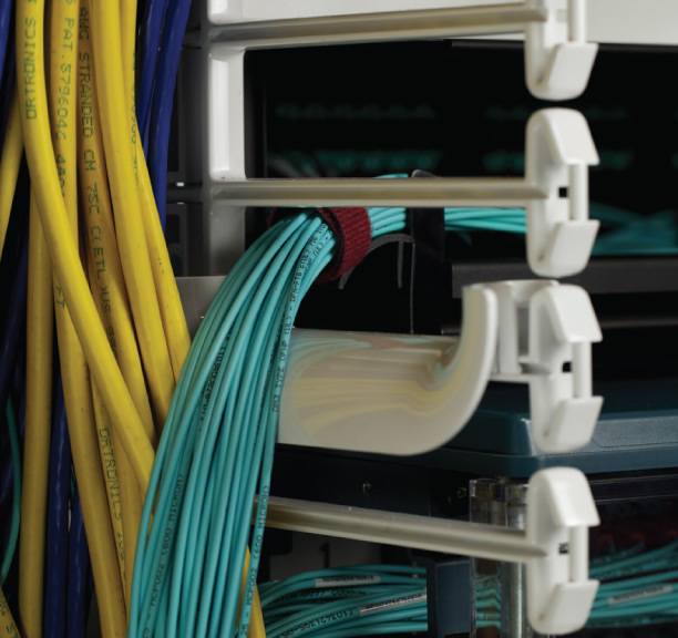
Fingers designed into Ortronics vertical cable managers support and protect cable at 1-inch intervals. Bend limiting clips snap onto fingers or side of fiber enclosure.
To maximize network performance, make informed decisions about the three parts of the infrastructure:
- structured cabling
- racks and cabinets
- cable management
Select a cabling solution with coengineered cable and connectivity to maximize channel performance. Look for flexible and scalable rack, cabinet and cable management solutions that can accommodate higher weight thresholds, have adjustable rails and wider vertical managers, along with integrated cable and airflow management options for better protection and airflow. The physical support solution should support copper and fiber media. Also, work with a manufacturer that is active in the standards. Standards usually take two to three years to develop, so these manufacturers will be aware of the upcoming requirements of new technology long before the standard is published.
Element #2: DATA CENTER DEPLOYMENT Time
Data centers are growing in size and complexity but often require faster deployment times. They must be able to adapt quickly and easily to support changing business requirements. Selecting infrastructure solutions that optimize time, result in faster deployments, reduced cost, and easier moves, adds and changes.
Since equipment will change several times during the life of the infrastructure, the infrastructure must be able to support new weight requirements, increasing port and cable densities, and cable media changes (i.e. replacing copper with fiber). At the same time, the infrastructure must be able to support common topologies like ToR (top of rack), MoR (middle of row) and EoR (end of row) along with future topologies.
A modular solution provides the foundation for a flexible and scalable building infrastructure. It combines the advantages of standardization with those of customization. The modular components must be designed to be integrated in order to maximize time savings in deployment, installation and future moves, adds and changes.
The modular design should be based around the rack or cabinet. Cable management and pathways should easily integrate with the rack or cabinet to make it truly modular. There are several time-savings features to look for in a rack or cabinet like being quick and easy to assemble. They should be able to be installed and correctly spaced, without having to have the vertical cable managers mounted. This provides room for equipment and cabling to be installed without the vertical manager in the way, hindering installation. Racks and cabinets with higher weight thresholds and taller heights will scale to new equipment needs instead of having to be replaced, saving both time and money.
Wide vertical cable management scale to future needs and save time when installing and dressing cable and when doing MAC work.
Other rack and cabinet modular components for effective airflow management and cooling should be available. Baffles that can be added for side-breathing equipment, blanking panels and brush grommets, etc. should be available to help passively manage airflow. This improves the efficiency of the existing cooling solution, especially when using a traditional hot-aisle/cold-aisle arrangement. If equipment densities are greater than 5 kW (kilowatts), consider a rack based cooling solution. New solutions like refrigerant-based close-coupled cooling are now available. When integrated within the enclosure, these solutions save time because they can easily be added to support higher densities when needed.
Wider vertical cable managers should be used to provide abundant room for cable densities into the future. They effectively save time because there is plenty of room to install, dress, and later manage the cable. If a rack or cabinet is loaded with patching equipment or 1U/2U servers, there will be a lot of cable to manage. If a rack or cabinet contains blade servers, there will be fewer cables, but cables still must be properly managed so airflow is not blocked to prevent heat accumulation. Blade servers often have hot-swappable components. The cable management must keep the cable from blocking these components, either in the front or back, depending on the server. Modular cable management should mount on the front or back of the rack or cabinet to be available where needed.
Cable pathways should be integrated with the rack and cabinet solution. Running cable overhead is a growing trend in data centers. It eliminates concerns about blocking airflow under a raised floor and makes the cable more accessible to do moves, adds and changes easier. When the overhead path (e.g. cable/basket tray, ladder rack) is integrated in the modular design, it will be quick and easy to install. Integration also minimizes the pathway elevation changes because it has been designed to work effortlessly with the rack or cabinet. Integrated pathways reduce installation time and minimize pathway elevation changes.

Integrated pathways reduce installation time and minimize pathway elevation changes.
Using pre-terminated copper and fiber cabling solutions are also a great way to save time during installation and later when performing moves, adds and changes. As fiber technology migrates from 10 Gigabit Ethernet (GbE) to faster applications like 40 and 100 Gigabit Ethernet, the ability to field terminate cable changes. 10GbE uses two fibers terminated with discrete connectors like the LC or SC connector. Beyond 10GbE, parallel transmission using multiple fibers for transmitting and multiple fibers for receiving is employed using the MPO connector, which terminates twelve fibers (or twenty-four fibers) in one connector. MPO connectors cannot be field-terminated. Pre-terminated fiber systems can facilitate the migration to higher speeds that will be required.
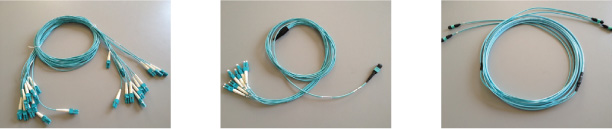
Pre-terminated fiber trunks save time and help migration beyond 10GbE. Trunks shown from left to right are LC-to-LC, LC-to-MPO and MPO-to-MPO.
Modular solutions should offer the following time-savings attributes:
- Modular racks and cabinets that assemble quickly, have adjustable rails, higher weight thresholds, and taller heights to easily accommodate new equipment
- Modular options for optimizing airflow management in a rack or cabinet and efficient cooling solutions (for 5kW density)
- Cable management that is easy to install, change and available where needed; in the front or back of the rack/cabinet
- Wide vertical cable managers that support changing cabling needs, minimize obstruction from the cables to support better airflow and can be installed at the end when dressing cable making equipment and cable installation easier
- Integrated pathways with rack/cabinet
- Pre-terminated solutions that allow for quick installation, easy moves, adds and changes, and easier migration to newer technologies
A modular solution designed so that all components work together optimizes installation and deployment time and will support future network changes, computing power and technology upgrades facilitating growth without major disruptions.
Element #3: DATA CENTER Space
In the past, the ability to adapt to future demands was done by oversizing the infrastructure system; letting the data center grow into its infrastructure over time. This is not efficient in capital or energy costs. Infrastructure systems must be designed for greater flexibility and scalability enabling the data center to be designed to be right-sized.
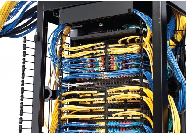
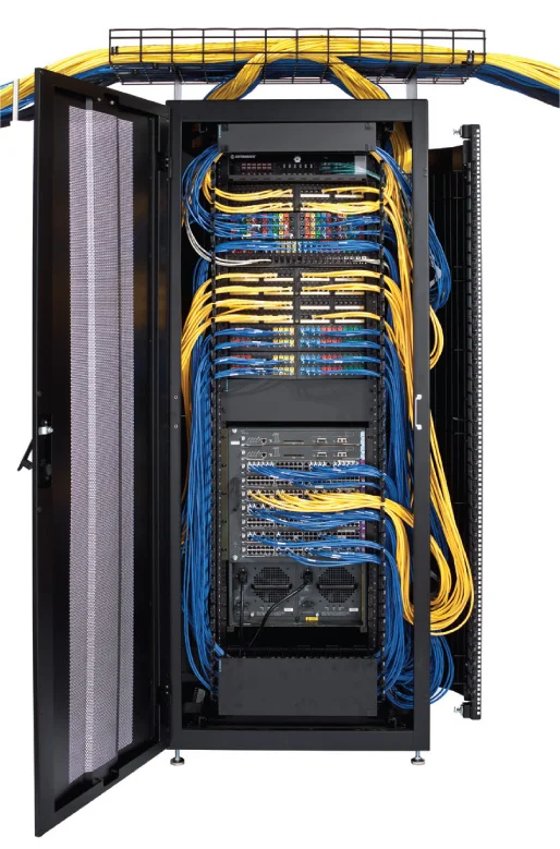
Space is a premium in the data center. The infrastructure system should optimize space. CISCO suggests adopting the rack as the basic building block for data center density as a best practice.
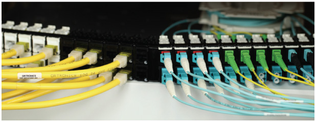
Multi-media and high density options optimize the use of space.
Port densities continue to increase making efficient space utilization even more important. Use high density connectivity options to optimize space while supporting large port densities. Mixed-media connectivity provides flexibility and scalability by allowing connectivity to be added as needed, eliminating the need to know the exact number of ports or type of connectors. Fiber cable is displacing existing copper cable. LC (2 fiber) connectors will be replaced by MPO (multi-fiber, typically 12 or 24 fibers) connectors as 10 GbE (gigabit Ethernet) migrates to 40 GbE and 100 GbE. Multi-media connectivity makes supporting the changing needs of newer technologies easier and optimizes space because multiple media-specific connectivity options (e.g. patching) are no longer needed. Cable management must support mixed media since each type of media has different characteristics (i.e. weight, pull-tension, bend radius, etc.). Cable with small ODs (outside diameter) will help optimize the use of space.
One basic best practice: adopt the rack as the basic building block for data center density. – Cisco Energy Efficient Data Center Solutions and Best Practices.
A new trend in data centers is to grow vertically. Traditional racks and cabinets are 7 feet tall. That is about 42 rack units (RU) to mount equipment; some 7 foot racks provide 45 rack units. Taller options should be available. A 9 foot rack can provide up to 58 RU, depending on the rack manufacturer, which is 38% more space (29% more space compared to a 7 foot, 45 RU rack) to mount equipment. Rack and cabinets must also have higher weight thresholds to hold additional or heavier equipment without having to be replaced. This allows more equipment in the same square foot area of the data center providing a better return-on investment for that floor space. An example of overhead patching. Real estate in racks and cabinets is valuable. Consider patching outside the rack or cabinet (e.g. above), reserving space inside for equipment, which uses the space more efficiently.
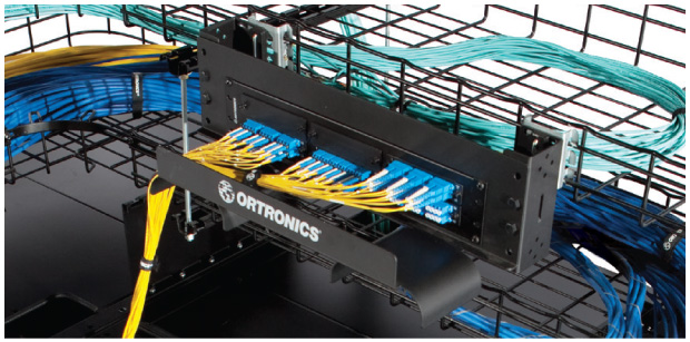
An example of overhead patching.
A flexible and scalable data center design will optimize space by selecting a physical infrastructure solution that has considered the needs of active equipment, cable management, connectivity, and integration with pathways. Physical infrastructure costs will be mitigated without sacrificing network performance. Optimizing space can also help defer CAPEX (capital expense) and reduce OPEX (operating expense) – right size, right time, right cost.
To optimize space in the data center consider the following:
- Use the rack or cabinet as your basic building block
- Select racks and cabinets with higher weight limits, sufficient depth and heights that support growing vertically
- Select cable management that can support existing cable density, provide ample room to grow, mitigates airflow restriction caused by cable, and is designed to support both copper and fiber
- Select connectivity that supports high density and mixed media
- Use cable with smaller OD
- Consider patching outside the rack and cabinet (e.g. overhead) to conserve space for equipment
- Select a rack or cabinet solution that easily integrates with overhead pathways
Element #4: DATA CENTER BUILD Experience
The quality of the data center build experience can be enhanced by selecting the right partner. The growing trend in data centers today is to outsource more. There are fewer employees requiring more to be done with less. Data centers are larger and more complex but must be up and running faster. Putting the pieces together can be very daunting. During the design phase, the data center design must provide guaranteed performance while providing flexibility and scalability for tomorrow’s needs. In general, the solutions should be modular for customization to meet specific needs and there may be special requirements that require additional customization. It is critical that the product in the solution work together seamlessly. During the installation phase, the solution must be easy to install, quick to deploy and easy to manage. It is also important to have a contractor that is qualified and has a history of quality installations. Logistics must be coordinated to guarantee delivery of what is needed when it is needed. Projects may also be global, which is why it is important to consider who you will work with.
Consider manufacturers that can provide resources to help coordinate the project through all stages – solution design, logistics, installation, etc. The solution may become the standard solution for other locations creating additional coordination with local support. The manufacturer should have the expertise with all components of the solution: close-coupled cooling, power, connectivity, cabling, racks and cabinets , cable management, and pathways – to guarantee that all pieces work seamlessly together. This expertise should be utilized to extend the equipment life, reduce cost and address the unique challenges in data centers, accomplished through one point of contact from the manufacturer.
Element #5: DATA CENTER DESIGN & PRODUCT Sustainability
Sustainability can mean many different things. Often it is associated with improving processes to avoid using up or totally destroying natural resources. The perceived importance of sustainability varies, but it is growing. Even if it is not a high priority for an organization today, working with a sustainable manufacturer doesn’t cost more and there are many benefits.
A manufacturer that has true sustainability goals will be ISO 14001 certified. The ISO 14001 standard details a best practice for proactive management. An ISO 140001 certified manufacturer becomes focused on continual improvement instead of mere compliance. Not only does this lead to better manufacturing processes, but it leads to better operations overall. By working with a sustainable manufacturer today, you are prepared for the day it becomes a priority for the organization or your customers.
Sustainability can also refer to the ability to last or continue for a long time. Sustainable designs offer choice and flexibility in space design, reducing installation time, material waste on site, etc. They should ensure optimal energy efficiency and performance. A manufacturer that has a commitment to sustainability will continually look for ways to improve their internal operations and will also be leaders in looking at solutions that result in a lower impact on the environment. This translates into data center solutions that should use a comprehensive approach; active and passive cooling, power distribution, air flow control, and racks or cabinets with cable management, to ensure optimal energy efficiency and performance. Consider products that simplify and reduce packaging. New technologies, like refrigerant-based close-coupled cooling, are now available. When integrated within the enclosure, these solutions provide a higher level of efficiency when compared to using CRACs (+95%) since they capture heat at its source. Another way to help reduce the impact on the environment is to use solutions derived from products with RoHS (Restriction of Hazardous Substances) compliance.
Not all sustainability claims are equal. Look for manufacturers that have internal, aggressive sustainable goals and are ISO 14001 certified. The manufacturer should also be committed to designing products and packaging that have less impact on the environment, like RoHS (Restriction of Hazardous Substances) compliance, improved energy efficiencies and less packaging to name a few.
Conclusion
A data center solution should be designed with connected infrastructure in mind; guaranteed performance, saving time, optimizing space, enhance experience by utilizing resources and enable sustainability.
Source: Data Center Design Best Practices: Efficiencies Beyond Power and Cooling, Legrand North America